Build Your Own RFID Attendance System
Learn how to build a working RFID attendance system with a Raspberry Pi Pico. Step-by-step wiring, code, and troubleshooting for students.
What you’re about to build
Ever tapped a card to get into a subway, a theme park, or your school’s key-card door? That’s RFID — Radio Frequency Identification — and in this project, you’re going to build your own working version of it.
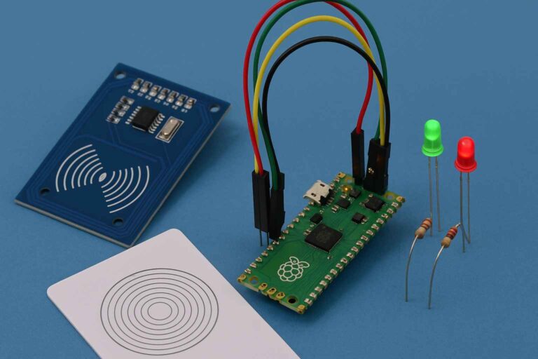
You’ll create a device that:
- Lets someone tap an RFID card near a sensor
- Instantly recognizes who they are
- Marks them “present” — but only once, so they can’t be marked twice
- Lights up a green LED to say “you’re in!”
- Blinks a red LED the whole time it’s waiting for the next card
It’s a great science fair project, a solid intro to electronics and coding, and honestly just really satisfying to watch work for the first time.
Skill level needed: Beginner. If you’ve never coded or wired anything before, you can still do this — just go slow and follow each step.
Time needed: 2–4 hours, spread over a few sessions is totally fine.
Cost: Roughly $15–$25 for everything, and you’ll be able to reuse the parts for other projects later.
1. How RFID actually works
Every RFID card has a tiny chip and a coil of wire inside it — no battery needed. The RFID reader (your sensor) constantly sends out a weak radio signal. When you bring the card close enough, that signal actually powers up the chip inside the card for a split second. The card then sends back a unique ID number, kind of like introducing itself: “Hi, I’m card #C345B514.”
Your microcontroller (the “brain” of your project) hears that ID number and decides what to do with it — in our case, checking if it belongs to someone on the attendance list.
That’s it. No internet, no Bluetooth, no batteries in the card. Just radio waves and a very short conversation.
2. What you’ll need
| # | Part | What it does | Roughly costs |
|---|---|---|---|
| 1 | Raspberry Pi Pico | The microcontroller — this is the “computer” running your code | $5 |
| 2 | MFRC522 RFID reader module | Reads the RFID cards | $6–8 (often comes with 2 cards/tags) |
| 3 | 2 RFID cards or key tags | What you tap on the reader | Usually included above |
| 4 | 1 green LED + 1 red LED | Visual feedback lights | $1 for a pack |
| 5 | 2 resistors (220 ohm) | Protect the LEDs from too much current | $1 for a pack |
| 6 | Breadboard | Lets you build circuits without soldering | $5 |
| 7 | Jumper wires (male-to-male & male-to-female) | Connects everything together | $5 for a pack |
| 8 | Micro-USB cable | Powers the Pico and uploads your code | You probably already have one |
You can find all of this on Amazon, SparkFun, or Adafruit. Search “Raspberry Pi Pico RFID kit” and you’ll usually find a bundle with everything except the LEDs and resistors.
Note: Don’t have a Raspberry Pi Pico? This same project also works on an ESP32 or ESP8266 board with small tweaks to the code. Ask a teacher or mentor if you’re not sure which board you have.
3. Understanding the wiring (before you touch anything)
Before plugging anything in, it helps to understand why each wire goes where it goes. The RFID reader talks to the Pico using something called SPI — think of it like a tiny, fast conversation lane with 4 wires: one for the clock (timing), and two for sending data back and forth.
Here’s the full wiring map:
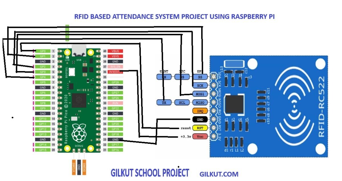
| MFRC522 pin | Connects to Pico pin | What it’s for |
|---|---|---|
| VCC | 3V3 (OUT) | Power — must be 3.3V, never 5V, or you can fry the reader |
| RST | GP0 | Resets the reader when needed |
| GND | GND | Ground (completes the circuit) |
| MISO | GP4 | Reader → Pico (incoming data) |
| MOSI | GP3 | Pico → Reader (outgoing data) |
| SCK | GP2 | Clock signal (timing) |
| SDA / SS / CS | GP1 | “I’m talking to you now” signal |
| IRQ | (leave unconnected) | Not used in this project |
And the two LEDs:
| Part | Connects to |
|---|---|
| Green LED (+ leg) | GP14, through a 220-ohm resistor |
| Green LED (– leg) | GND |
| Red LED (+ leg) | GP15, through a 220-ohm resistor |
| Red LED (– leg) | GND |
Tip: LEDs only work one direction. The longer leg is positive (+) and goes toward the resistor/GPIO pin. The shorter leg is negative (–) and goes toward GND. If your LED doesn’t light up, try flipping it around before assuming something’s broken.
⚠️ The one rule you must not break: The MFRC522 module runs on 3.3 volts. The Pico’s 3V3 pin is exactly right. Never connect it to a 5V pin — even for a second — or you risk permanently damaging the reader.
SPI wires are physically connected to:
| Parameter | Meaning | Physically wired to |
|---|---|---|
sck=2 | Serial Clock line | MFRC522 SCK pin → GPIO 2 |
mosi=3 | Data out from Pico to reader (Master-Out-Slave-In) | MFRC522 MOSI pin → GPIO 3 |
miso=4 | Data in from reader to Pico (Master-In-Slave-Out) | MFRC522 MISO pin → GPIO 4 |
rst=0 | Reset line — pulses the module to reset it | MFRC522 RST pin → GPIO 0 |
cs=1 | Chip Select — tells the module “you’re the one I’m talking to right now” | MFRC522 SDA / SS / CS pin → GPIO 1 |
baudrate=100000 | SPI communication speed (100 kHz) — not a pin, just a speed setting | — |
4. Setting up your software
Before writing any code, your Pico needs two things installed:
Step 1 — Install MicroPython on your Pico
- Download the MicroPython
.uf2firmware file for the Raspberry Pi Pico from the official micropython.org downloads page. - Hold down the BOOTSEL button on your Pico, plug it into your computer with the USB cable, then release the button. It should show up like a USB drive.
- Drag and drop the
.uf2file onto that drive. The Pico will restart automatically — now it understands Python!
Step 2 — Install an editor
Download Thonny (thonny.org) — it’s free, beginner-friendly, and made specifically for MicroPython projects like this one. Open it, and under the bottom-right corner, select your Pico as the interpreter.
Step 3 — Add the RFID library
Your Pico needs a small helper file called mfrc522.py that knows how to “speak” to the RFID reader. Search “micropython mfrc522 library” to find one (there are a few free community versions), then use Thonny’s file manager to upload mfrc522.py onto your Pico, alongside your main code.
5. The code
Here’s the full program. Save it as main.py so it runs automatically every time your Pico powers on.
python
from mfrc522 import MFRC522
from machine import Pin
import utime

# Initialize RFID
rdr = MFRC522(
    sck=2,
    mosi=3,
    miso=4,
    rst=0,
    cs=1,
    baudrate=100000
)

# LED setup
green_led = Pin(14, Pin.OUT)
red_led = Pin(15, Pin.OUT)
green_led.off()
red_led.off()

# Registered UID database (replace with your own UID lists)
students = {
    "C345B514": "PULKIT KUMAR SINHA",
    "337CA2A9": "MANISH KUMAR SINHA",
    "DEADBEEF": "Charlie"
}

marked_present = []

print("RFID Attendance System Ready!")

while True:
    (status, tag_type) = rdr.request(rdr.REQIDL)
    if status == rdr.OK:
        (status, uid_bytes) = rdr.SelectTagSN()
        if status == rdr.OK:
            uid_str = ''.join(['%02X' % b for b in uid_bytes])
            print("Card UID:", uid_str)
            if uid_str in students:
                name = students[uid_str]
                if name not in marked_present:
                    marked_present.append(name)
                    time_str = "%02d:%02d:%02d" % utime.localtime()[3:6]
                    print(f"{name} marked present at {time_str}")
                    # Green LED blink
                    for _ in range(2):
                        green_led.on()
                        utime.sleep(0.3)
                        green_led.off()
                        utime.sleep(0.3)
                else:
                    print(f"{name} already marked present.")
            else:
                print("Unknown UID")
        else:
            print("Error reading UID")
    else:
        # Blink red LED to show system is waiting
        red_led.on()
        utime.sleep(0.1)
        red_led.off()
        utime.sleep(0.1)
What’s actually happening, line by line (in plain English)
rdr = MFRC522(...)— This tells your Pico exactly which pins the reader is wired to (see the table above), and sets the communication speed.students = {...}— This is your “class roster.” Each RFID card’s unique ID (UID) is matched to a name. You’ll replace this with your own students’ card IDs.while True:— This loop runs forever, constantly checking: “Is there a card nearby right now?”rdr.request(...)— Politely asks, “anyone there?” If nothing responds, the red LED blinks to show the system is alive and waiting.rdr.SelectTagSN()— If a card answered, this grabs its unique ID number.- The
if uid_str in students:check — Looks up whether that ID belongs to someone on your list. - The
if name not in marked_present:check — This is the clever part: it stops the same person from being marked present twice. - The green LED blink — A little celebration for a successful, new attendance mark.
6. Finding your own card’s UID
The code above uses example UIDs like "C345B514" — those won’t match your cards. Here’s how to find your real ones:
- Upload and run the code as-is.
- In Thonny’s output window, tap one of your RFID cards on the reader.
- You’ll see a line like
Card UID: A1B2C3D4printed out — that’s your card’s real ID! - Copy that ID into your
studentsdictionary and give it a name. - Repeat for every card you want to register.
7. Testing your project
Run through this checklist once everything is wired and uploaded:
- Power on the Pico — the console should print “RFID Attendance System Ready!”
- With no card nearby, the red LED should be blinking steadily
- Tap a registered card — you should see a name printed, a timestamp, and the green LED blink twice
- Tap that same card again — it should say “already marked present” and the LED should not blink again
- Tap an unregistered card — it should print “Unknown UID” and nothing else happens
If all five of those work, congratulations — your system is fully functional! 🎉
8. Troubleshooting common problems
| Problem | Likely cause | Try this |
|---|---|---|
| Nothing prints in the console at all | Wrong pins wired, or mfrc522.py missing | Double-check every wire against the table in Section 3; confirm mfrc522.py is uploaded |
| Red LED never blinks | LED wired backwards, or wrong GPIO pin | Flip the LED around; confirm it’s on GP15 |
| Card is never recognized, even a registered one | UID typed wrong (case-sensitive!) | Re-scan the card and copy the UID exactly as printed |
| Reader gets warm or stops responding | Accidentally powered with 5V instead of 3.3V | Unplug immediately, recheck VCC wiring, may need a new reader module |
| Green LED blinks but wrong/no name shows | Dictionary key doesn’t exactly match the printed UID | Compare carefully — even one wrong character won’t match |
9. Make it your own (great science fair upgrades)
Once the basic version works, here are ways to level it up:
- Add a real-time clock (RTC) module so your timestamps are accurate even after the Pico restarts
- Log attendance to an SD card or a file, so records aren’t lost when it powers off
- Add a small screen (OLED display) to show names directly on the device instead of just the console
- Add a buzzer for a satisfying “beep” alongside the LED
- Connect it to Wi-Fi (using a Pico W) to send attendance data to a spreadsheet or app
- Reset the list automatically at a certain time each day, so it’s ready for tomorrow
Any one of these upgrades makes for a great “what I’d do next” section in a science fair report — judges love seeing that you understand the limitations of your own project and have real ideas to fix them.
10. Quick glossary
- RFID — Radio Frequency Identification; a way to identify objects wirelessly using radio waves
- UID — Unique Identifier; the one-of-a-kind ID number every RFID card has
- Microcontroller — A tiny computer built to run one program and control hardware (your Pico)
- SPI — Serial Peripheral Interface; the “language” the reader and Pico use to talk to each other
- GPIO — General Purpose Input/Output; the pins on your board you can control with code
- MicroPython — A version of the Python programming language made to run on small microcontrollers
You just built a real, working piece of embedded electronics — the same core technology used in transit cards, employee badges, and hotel key cards. Nice work.