We are going to use Temperature and Humidity Sensor DHT11 with Connecting Temperature and Humidity Sensor DHT11 to ESP8266 NodeMCU.Monitoring environmental conditions like temperature and humidity is crucial for various DIY projects, smart home automation, and weather stations. In this guide, we’ll show you how to connect a DHT11 sensor to an ESP8266 NodeMCU and read temperature and humidity data effortlessly.
What is DHT11 Sensor?
The DHT11 is a simple and affordable sensor designed for measuring temperature and humidity. Its compact size and ease of use make it popular among hobbyists and beginners. While it may not be as precise as advanced sensors, it’s an excellent choice for most basic applications.
Key Features of DHT11:
Measures temperature in the range of 0°C to 50°C.
Measures humidity in the range of 20% to 90%.
Operates at a voltage range of 3V to 5V.
Comes with a single-wire digital interface, making it easy to connect.
What is ESP8266 NodeMCU?
The ESP8266 NodeMCU is a low-cost Wi-Fi-enabled microcontroller. It is highly versatile and widely used for IoT (Internet of Things) projects. With built-in Wi-Fi capability, you can send sensor data to online platforms or control devices remotely.
Why Combine DHT11 and NodeMCU? The DHT11 and NodeMCU pair perfectly for projects requiring remote monitoring of environmental conditions. For example:
Create alerts based on temperature or humidity changes.
Build a Wi-Fi-connected weather station.
Automate home cooling or humidifying systems.
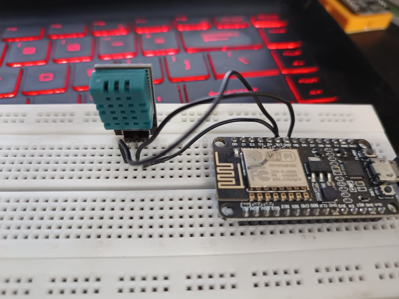
DHT11 CONNECTION PINS (Wiring DHT11 with NodeMCU)
DHT11 has 3 terminals. To connect the DHT11 sensor to the NodeMCU, you’ll only need a few components and simple wiring. Here’s what you’ll need:
Required Components:
ESP8266 NodeMCU.
DHT11 sensor (or a DHT11 module).
Jumper wires.
Breadboard (optional).
Wiring Diagram:
VCC on the DHT11 connects to 3V on the NodeMCU.
GND on the DHT11 connects to GND on the NodeMCU.
Data Pin on the DHT11 connects to D5 (or any GPIO pin you choose) on the NodeMCU.
If you’re using a DHT11 module with a built-in pull-up resistor, no additional components are needed. Otherwise, you may need a 10k ohm pull-up resistor between the Data Pin and VCC.
PIN NO.
NAME
CONNECTED TO
1
Vcc
3.3V of NodeMCU
2
DATA PIN
D5 of NodeMCU
3
G (Ground)
GND of NodeMCU
CODE
#include "DHT.h"
#define DHTPIN D2
#define DHTTYPE DHT11
DHT dht(DHTPIN, DHTTYPE, 15); // Initialize DHT sensor

void setup()
 {
  dht.begin();        // Init DHT
  Serial.begin(9600);
 }
 void loop()
 {
   int h = dht.readHumidity(); // Reading temperature and humidity
   int t = dht.readTemperature();  // Read temperature as Celsius

   Serial.print("Humidity: ");
  Serial.print(h);
  Serial.print(" %\t");
  Serial.print("Temperature: ");
  Serial.print(t);
  Serial.println(" *C");
  delay(2000); // Delay between readings.
 }
Explanation of CODE
Here, we give the easy explanation by breaking down the complete code line by line
Code
Explanation
#include "DHT.h"
This line includes the DHT library, which contains the functions needed to interact with the DHT sensor.
#define DHTPIN D2
This defines DHTPIN as D2, specifying that the DHT sensor is connected to the D2 pin of the microcontroller.
#define DHTTYPE DHT11
This sets the type of DHT sensor being used as DHT11. If you are using a different model, you need to change this (e.g., DHT22).
DHT dht(DHTPIN, DHTTYPE, 15);
Creates a DHT object with the pin D2, sensor type DHT11, and a custom sampling rate of 15 milliseconds.
void setup()
The setup() function runs once when the program starts. It’s used to initialize components like the sensor and serial communication.
{
Opens the code block for the setup() function.
dht.begin();
Initializes the DHT sensor so it’s ready to start reading data.
Serial.begin(9600);
Starts the serial communication at a baud rate of 9600, allowing data to be sent to your computer for display.
}
Closes the setup() function block.
void loop()
The loop() function runs repeatedly, enabling the sensor to keep reading and sending data.
{
Opens the code block for the loop() function.
int h = dht.readHumidity();
Reads the humidity value from the DHT sensor and stores it in the variable h.
int t = dht.readTemperature();
Reads the temperature in Celsius from the DHT sensor and stores it in the variable t.
Serial.print("Humidity: ");
Sends the text “Humidity: ” to the serial monitor so you can see the context of the humidity value.
Serial.print(h);
Prints the humidity value (h) to the serial monitor.
Serial.print(" %\t");
Adds the percentage symbol and a tab space for better formatting.
Serial.print("Temperature: ");
Sends the text “Temperature: ” to the serial monitor for context about the temperature value.
Serial.print(t);
Prints the temperature value (t) to the serial monitor.
Serial.println(" *C");
Adds “°C” to indicate the unit of temperature and moves to the next line in the serial monitor for readability.
delay(2000);
Pauses the program for 2000 milliseconds (2 seconds) before taking the next reading, to give time between measurements.
}
Closes the loop() function block.
Setting Up the Arduino IDE
To program the NodeMCU, we’ll use the Arduino IDE. Follow these steps:
Install the ESP8266 Board Package:
Open Arduino IDE and go to File > Preferences.
In the “Additional Boards Manager URLs” field, paste this URL: http://arduino.esp8266.com/stable/package_esp8266com_index.json.
Go to Tools > Board > Boards Manager, search for “ESP8266,” and install it.
Install the DHT Library:
Go to Sketch > Include Library > Manage Libraries.
Search for “DHT” and install the library by Adafruit.
Connect the NodeMCU to Your Computer:
Use a micro USB cable to connect the NodeMCU.
Select the correct port under Tools > Port.
Uploading the Code
Once you’ve wired everything and set up the Arduino IDE, you’re ready to upload the code. Make sure the DHT library is included and adjust the pin definition (e.g., D2) to match your wiring.
Testing the Setup
After uploading the code:
Open the Serial Monitor in Arduino IDE (Ctrl+Shift+M).
Set the baud rate to 9600 to match the code.
You should see real-time temperature and humidity readings.
Applications of DHT11 and NodeMCU
The combination of DHT11 and NodeMCU has endless possibilities. Here are some ideas:
IoT Weather Station: Monitor temperature and humidity online using services like ThingSpeak or Blynk.
Smart Greenhouse: Automate irrigation or ventilation based on real-time humidity and temperature levels.
Room Climate Monitor: Keep an eye on indoor conditions and adjust air conditioners or humidifiers accordingly.
Troubleshooting Tips
No Data in Serial Monitor? Check the wiring and ensure the correct pin is defined in the code.
Unstable Readings? Verify the pull-up resistor connection and avoid long jumper wires.
Error Messages While Uploading Code? Ensure the correct board and port are selected in the Arduino IDE.
Conclusion
Connecting a DHT11 sensor to an ESP8266 NodeMCU is an excellent way to start exploring IoT projects. It’s simple, affordable, and offers valuable insights into environmental conditions. Whether you’re building a weather station or automating your home, this duo provides a solid foundation. Try it out and take your DIY skills to the next level!
Learn everything about thermistor sensors in this in-depth guide. Explore types, working principles, applications, advantages, limitations, and comparisons with thermocouples
Learn how to use a soil moisture sensor with ESP8266 NodeMCU for smart irrigation systems. This guide covers sensor pinout, wiring, coding, and a practical project to automate watering while monitoring moisture levels remotely.
The BME280 sensor module is a compact and accurate environmental sensor for measuring temperature, humidity, and pressure. Perfect for IoT, weather stations, and DIY projects, learn how to use it with Arduino or Raspberry Pi in this beginner-friendly guide.
Learn how to connect your ESP8266 module to a Wi-Fi network with this comprehensive guide. Perfect for beginners, featuring hardware setup, Arduino IDE configuration, and troubleshooting tips