Create an advanced 2-digit counter project using Raspberry Pi Pico with a 7-segment display, buzzer alerts, and blinking LEDs. Ideal for students and hobbyists!
✅ Level: Intermediate
🧠 Skills Learned: 7-segment interfacing, button handling, buzzer control, LED blinking, MicroPython logic
🕒 Estimated Time: 2–3 hours
🧰 Components Required
| Component | Quantity |
|---|---|
| Raspberry Pi Pico (or Pico W) | 1 |
| 7-Segment Display (Common Cathode) | 1 |
| 220Ω Resistors (for segments) | 8 |
| Push Buttons | 5 |
| Buzzer (Piezo or Passive) | 1 |
| Green LED | 1 |
| Red LED | 1 |
| Breadboard & Jumper Wires | 1 set |
| Micro USB Cable | 1 |
| Computer with Thonny IDE | 1 |
🖼️ Project Overview
This project builds a 2-digit counter (00 to 99) with the following features:
- 🔼 Count up or 🔽 count down using buttons
- ⚙️ Enter Set Mode to manually adjust digits
- 🔁 Reset the counter anytime
- 🔊 Buzzer sounds for feedback and 3-second alert on reaching max/min limit
- 💡 Green LED blinks during counting
- 🚨 Red LED lights up when limit is reached
🧠 Understanding the Logic
✅ Button Functions:
| Button | GPIO | Function |
|---|---|---|
Up (btn_up) | 10 | Increment counter |
Down (btn_down) | 11 | Decrement counter |
Reset/Confirm (btn_confirm) | 12 | Reset counter / Confirm set mode |
Select Digit (btn_select) | 13 | Switch between tens/ones during set mode |
Enter Set Mode (btn_setmode) | 14 | Toggle set mode |
🧠 Special Features:
Set Mode: Lets you set the tens and ones digits separatelyLimit Alert: On reaching 99 or 00, a 3-second continuous beep and red LED alert are triggered only once
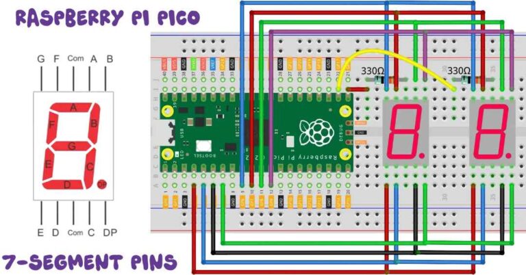
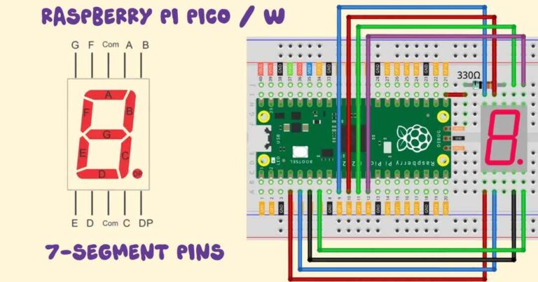
🔌 Circuit Diagram (Wiring)
📺 7-Segment Display:
Connect segment pins a to dp to GPIO 0–7 through 220Ω resistors.
| Segment | GPIO |
|---|---|
| a | 0 |
| b | 1 |
| c | 2 |
| d | 3 |
| e | 4 |
| f | 5 |
| g | 6 |
| dp | 7 |
Digit selection pins (common cathode control):
- Digit 1 (Tens): GPIO 16
- Digit 2 (Ones): GPIO 17
🔘 Buttons:
Connect one side of each button to:
- GPIO 10 to 14 as listed above
- Other side to GND
Add internal pull-down via software (MicroPython handles this)
🔊 Buzzer:
- Connect buzzer +ve to GPIO 15
- GND to negative rail
💡 LEDs:
- Green LED → GPIO 18 (with 220Ω resistor)
- Red LED → GPIO 19 (with 220Ω resistor)
💻 MicroPython Code
👉 Download and install Thonny IDE
👉 Flash MicroPython firmware to your Pico
👉 Create a new file named counter.py, then copy and paste the full code from here:
from machine import Pin, PWM
import utime

# Segment pins a to dp (GPIO 0 to 7)
segment_pins = [0, 1, 2, 3, 4, 5, 6, 7]
segments = [Pin(pin, Pin.OUT) for pin in segment_pins]

# Digit control (common cathode)
digit_pins = [Pin(16, Pin.OUT), Pin(17, Pin.OUT)]

# Buzzer setup (PWM on GPIO 15)
buzzer = PWM(Pin(15))

# LEDs
green_led = Pin(18, Pin.OUT)
red_led = Pin(19, Pin.OUT)

# Buttons with pull-down resistors
btn_up = Pin(10, Pin.IN, Pin.PULL_DOWN)
btn_down = Pin(11, Pin.IN, Pin.PULL_DOWN)
btn_confirm = Pin(12, Pin.IN, Pin.PULL_DOWN)  # RESET
btn_select = Pin(13, Pin.IN, Pin.PULL_DOWN)   # STOP
btn_setmode = Pin(14, Pin.IN, Pin.PULL_DOWN)  # SET MODE

# Digit patterns for 0–9
digit_patterns = [
    (1,1,1,1,1,1,0,0), (0,1,1,0,0,0,0,0),
    (1,1,0,1,1,0,1,0), (1,1,1,1,0,0,1,0),
    (0,1,1,0,0,1,1,0), (1,0,1,1,0,1,1,0),
    (1,0,1,1,1,1,1,0), (1,1,1,0,0,0,0,0),
    (1,1,1,1,1,1,1,0), (1,1,1,1,0,1,1,0)
]

# Variables
counter = 0
mode = None
set_mode = False
selected_digit = 0
last_tick = utime.ticks_ms()
limit_reached = False

# ---------------- Buzzer Functions ---------------- #
def beep(freq=1000, duration=0.05):
    buzzer.freq(freq)
    buzzer.duty_u16(1000)
    utime.sleep(duration)
    buzzer.duty_u16(0)

def long_beep():
    green_led.value(0)      # Turn off green
    red_led.value(1)        # Red ON
    buzzer.freq(1000)
    buzzer.duty_u16(2000)
    utime.sleep(3)
    buzzer.duty_u16(0)
    red_led.value(0)        # Red OFF after 3s

# ---------------- Display Function ---------------- #
def display_digit(pos, digit, blink=False):
    pattern = digit_patterns[digit]
    # Blinking segment logic
    if blink and utime.ticks_ms() % 400 < 200:
        pattern = (0,0,0,0,0,0,0,0)
    for seg, val in zip(segments, pattern):
        seg.value(val)
    digit_pins[0].value(1)
    digit_pins[1].value(1)
    digit_pins[pos].value(0)
    utime.sleep_ms(5)
    digit_pins[pos].value(1)

# ---------------- Main Loop ---------------- #
while True:
    # -------- SET MODE -------- #
    if btn_setmode.value() and not set_mode:
        set_mode = True
        selected_digit = 0
        mode = None
        utime.sleep(0.3)

    if set_mode:
        if btn_up.value():
            if selected_digit == 0 and counter < 90:
                counter += 10
                beep(1000)
            elif selected_digit == 1 and counter % 10 < 9:
                counter += 1
                beep(1000)
            utime.sleep(0.2)

        if btn_down.value():
            if selected_digit == 0 and counter >= 10:
                counter -= 10
                beep(400)
            elif selected_digit == 1 and counter % 10 > 0:
                counter -= 1
                beep(400)
            utime.sleep(0.2)

        if btn_select.value():
            selected_digit = 1 - selected_digit
            beep(600)
            utime.sleep(0.3)

        if btn_confirm.value():
            set_mode = False
            beep(1200)
            utime.sleep(0.3)

        # Show digits with blinking effect on selected one
        tens = counter // 10
        ones = counter % 10
        for _ in range(10):
            display_digit(0, tens, blink=(selected_digit == 0))
            display_digit(1, ones, blink=(selected_digit == 1))
        continue

    # -------- BUTTON ACTIONS -------- #
    if btn_up.value():
        mode = 'up'
        utime.sleep(0.3)

    if btn_down.value():
        mode = 'down'
        utime.sleep(0.3)

    if btn_confirm.value():  # RESET button
        counter = 0
        mode = None
        limit_reached = True
        beep(1500)
        green_led.value(0)   # TURN OFF GREEN LED
        red_led.value(0)     # TURN OFF RED LED
        utime.sleep(0.3)

    if btn_select.value():  # STOP button
        mode = None
        green_led.value(1)   # TURN GREEN LED SOLID ON
        red_led.value(0)
        utime.sleep(0.3)

    # -------- COUNTING -------- #
    if mode and utime.ticks_diff(utime.ticks_ms(), last_tick) >= 1000:
        if mode == 'up':
            if counter < 99:
                counter += 1
                beep(1000)
                limit_reached = False
            elif counter == 99 and not limit_reached:
                long_beep()
                limit_reached = True
        elif mode == 'down':
            if counter > 0:
                counter -= 1
                beep(400)
                limit_reached = False
            elif counter == 0 and not limit_reached:
                long_beep()
                limit_reached = True
        last_tick = utime.ticks_ms()

    # -------- LED LOGIC -------- #
    if not limit_reached and mode is not None:
        green_led.value(utime.ticks_ms() % 500 < 250)  # blink every 250ms

    # -------- DISPLAY -------- #
    tens = counter // 10
    ones = counter % 10
    for _ in range(10):
        display_digit(0, tens)
        display_digit(1, ones)
🚦 How It Works
1. Normal Mode
Press Up or Down to start counting. Green LED blinks.
2. Set Mode
Press Set Mode to enter configuration.
Use Select to switch between digits, and Up/Down to change the value.
Press Confirm to save and exit.
3. Limit Reached
- When counter reaches
99or00:- A 3-second long beep plays
- Green LED turns off
- Red LED glows solid
- Press
Resetto start fresh.
🧪 Testing Checklist
✅ Power on your Pico
✅ Confirm all segments light correctly
✅ Test buttons one-by-one
✅ Check beep and LED behavior at limit values
✅ Set mode should allow digit selection and editing
📸 Final Output
- Display: Shows 2-digit counter live
- Buttons: Easily adjust and control
- Buzzer: Click feedback + alert
- LEDs: Visually signal counting and error
💡 Full Code Explanation: 2-Digit Counter with Buzzer & LED Alerts
📦 1. Import Required Modules
pythonCopyEditfrom machine import Pin, PWM
import utime
Pin: Used to control GPIO pins (input/output).PWM: Pulse Width Modulation, used to control buzzer tone.utime: Time-related functions likesleep,ticks_ms().
🔌 2. Define 7-Segment Display Pins
pythonCopyEditsegment_pins = [0, 1, 2, 3, 4, 5, 6, 7]
segments = [Pin(pin, Pin.OUT) for pin in segment_pins]
- Segment
a to dpare connected to GPIO 0–7. - Each pin is set as an output to control the LED segments.
🧮 3. Control Common Cathode (Digit Pins)
pythonCopyEditdigit_pins = [Pin(16, Pin.OUT), Pin(17, Pin.OUT)]
- GPIO 16 and 17 control which digit (tens or ones) is active.
- Only one digit is lit at a time using multiplexing.
🔊 4. Buzzer Setup
pythonCopyEditbuzzer = PWM(Pin(15))
- A PWM-controlled buzzer is connected to GPIO 15.
- We use PWM to produce tones and beeps.
🔘 5. Button Setup with Pull-Downs
pythonCopyEditbtn_up = Pin(10, Pin.IN, Pin.PULL_DOWN)
btn_down = Pin(11, Pin.IN, Pin.PULL_DOWN)
btn_confirm = Pin(12, Pin.IN, Pin.PULL_DOWN)
btn_select = Pin(13, Pin.IN, Pin.PULL_DOWN)
btn_setmode = Pin(14, Pin.IN, Pin.PULL_DOWN)
- 5 buttons are connected to GPIO 10–14.
- Each button is configured as input with an internal pull-down resistor (default LOW until pressed).
🧮 6. 7-Segment Digit Patterns
pythonCopyEditdigit_patterns = [
    (1,1,1,1,1,1,0,0),  # 0
    (0,1,1,0,0,0,0,0),  # 1
    ...
    (1,1,1,1,0,1,1,0)   # 9
]
- Each digit is represented by a tuple of 1s and 0s.
- Each position corresponds to a segment (
atog, anddp). 1means ON,0means OFF.
📊 7. Initialize Variables
pythonCopyEditcounter = 0
mode = None
set_mode = False
selected_digit = 0
last_tick = utime.ticks_ms()
limit_reached = False
counter: Holds current number (0–99).mode: ‘up’ or ‘down’ for counting.set_mode: True when we’re editing digits manually.selected_digit: 0 (tens), 1 (ones).last_tick: Used to check 1-second intervals.limit_reached: Prevents repeated 3s beep at max/min.
🔔 8. Buzzer Functions
pythonCopyEditdef beep(freq=1000, duration=0.05):
    buzzer.freq(freq)
    buzzer.duty_u16(1000)
    utime.sleep(duration)
    buzzer.duty_u16(0)
- Makes a short beep.
- Adjust
freqanddurationto change tone and length.
pythonCopyEditdef long_beep():
    green_led.value(0)
    red_led.value(1)
    buzzer.freq(1000)
    buzzer.duty_u16(2000)
    utime.sleep(3)
    buzzer.duty_u16(0)
    red_led.value(0)
- Plays a 3-second long alert.
- Turns off green LED and turns on red LED.
🖥️ 9. Display a Digit
pythonCopyEditdef display_digit(pos, digit, blink=False):
    pattern = digit_patterns[digit]
    if blink and utime.ticks_ms() % 400 < 200:
        pattern = (0,0,0,0,0,0,0,0)
    for seg, val in zip(segments, pattern):
        seg.value(val)
    digit_pins[0].value(1)
    digit_pins[1].value(1)
    digit_pins[pos].value(0)
    utime.sleep_ms(5)
    digit_pins[pos].value(1)
- Lights up a digit (tens or ones).
- Uses multiplexing: activates only one digit at a time.
blink=Truemakes it flash (used in set mode).
🧠 10. Main Loop Starts
pythonCopyEditwhile True:
Everything inside this loop runs again and again — it’s where logic happens.
⚙️ 11. Enter Set Mode
pythonCopyEditif btn_setmode.value() and not set_mode:
    set_mode = True
    selected_digit = 0
    mode = None
    utime.sleep(0.3)
- If you press the Set button, enter set mode.
- Reset
modeso normal counting stops.
🧾 12. Inside Set Mode
pythonCopyEditif set_mode:
    ...
    continue
- Inside this block, user can adjust digits:
btn_up/down: change selected digitbtn_select: switch between tens and onesbtn_confirm: exit set mode
display_digit(..., blink=True)flashes the active digit
⬆️⬇️ 13. Change Mode with Buttons
pythonCopyEditif btn_up.value():
    mode = 'up'
- Start counting up or down.
- Resets previous mode and sets new one.
🔁 14. Reset Button
pythonCopyEditif btn_confirm.value():
    counter = 0
    mode = None
    limit_reached = True
    beep(1500)
- Resets counter to 0.
limit_reached = Trueprevents long beep at 0.
⌛ 15. Counting Every 1 Second
pythonCopyEditif mode and utime.ticks_diff(utime.ticks_ms(), last_tick) >= 1000:
- Checks if 1 second passed since last tick
- If yes, update counter and play a beep
Count Up:
pythonCopyEditif counter < 99:
    counter += 1
    beep(1000)
    limit_reached = False
elif counter == 99 and not limit_reached:
    long_beep()
    limit_reached = True
Count Down:
pythonCopyEditif counter > 0:
    counter -= 1
    beep(400)
    limit_reached = False
elif counter == 0 and not limit_reached:
    long_beep()
    limit_reached = True
- Plays short beep every count
- Plays 3s long beep once on reaching limit
- Prevents repeat with
limit_reachedflag
💡 16. Green LED Blinking
pythonCopyEditif not limit_reached:
    green_led.value(utime.ticks_ms() % 500 < 250)
- Blinks green LED only if not in limit reached mode
- On for 250ms, off for 250ms → Blinking effect
📺 17. Display Both Digits
pythonCopyEdittens = counter // 10
ones = counter % 10
for _ in range(10):
    display_digit(0, tens)
    display_digit(1, ones)
- Splits the counter into tens and ones
- Displays both by quickly switching digits (multiplexing)
🔌 CONNECTION SUMMARY
📺 1. 7-Segment Display (Common Cathode)
| Segment | GPIO Pin | Note |
|---|---|---|
| a | GPIO 0 | Connect via 220Ω resistor |
| b | GPIO 1 | “” |
| c | GPIO 2 | “” |
| d | GPIO 3 | “” |
| e | GPIO 4 | “” |
| f | GPIO 5 | “” |
| g | GPIO 6 | “” |
| dp | GPIO 7 | (optional, not used in display logic) |
| Digit Control | GPIO Pin | Purpose |
|---|---|---|
| Tens digit | GPIO 16 | Enable left digit |
| Ones digit | GPIO 17 | Enable right digit |
⚠️ Use current-limiting resistors (220Ω) between GPIO and segment pins to avoid damage.
🔘 2. Buttons (with internal pull-downs in code)
| Button Function | GPIO Pin | Description |
|---|---|---|
| Count Up | GPIO 10 | Increments counter |
| Count Down | GPIO 11 | Decrements counter |
| Reset / Confirm | GPIO 12 | Resets counter / exits set mode |
| Select Digit | GPIO 13 | Toggles between tens/ones |
| Enter Set Mode | GPIO 14 | Activates manual set mode |
🔧 Connect one side of each button to GND
🧠 The code usesPin.PULL_DOWN, so no need for external resistors.
🔊 3. Buzzer
| Description | GPIO Pin | Connection |
|---|---|---|
| Buzzer (+ve / Signal) | GPIO 15 | Connect directly or through small transistor if needed |
| Buzzer (GND) | GND | Connect to ground rail |
⚠️ Use passive buzzer for tone control using PWM.
💡 4. LEDs
| LED Color | GPIO Pin | Description |
|---|---|---|
| Green | GPIO 18 | Blinks during normal counting |
| Red | GPIO 19 | Glows solid when limit is reached (00 or 99) |
🔧 Use 220Ω resistor in series with each LED.
🛠️ Power & General Notes
- Power Pico via micro-USB cable
- Connect all GND points (Pico, buttons, LEDs, buzzer) to common ground rail on breadboard
✅ Summary
This project teaches you:
- How to control a 7-segment display
- How to read buttons and use set mode
- How to control a buzzer with PWM
- How to blink LEDs and create alerts
- How to build smart logic using MicroPython
📦 Download
💾 Get the MicroPython .py file + wiring diagram (if needed):
[GitHub Project Link or Google Drive folder] ← Upload your files here and share
🙌 Conclusion
You’ve built a professional-style 2-digit counter system with:
✅ Display
✅ Sound
✅ LED indicators
✅ Smart control
This project teaches how to combine hardware control and MicroPython programming effectively. It’s perfect for electronics students and hobbyists ready to explore deeper into microcontroller logic.