🔢 Build a 2-Digit 7-Segment Display Counter with Raspberry Pi Pico
An easy electronics project for students
🧠 What You’ll Learn
- What a 7-segment display is
- How to control it using Raspberry Pi Pico
- How to display numbers from 00 to 99
- How to write and run MicroPython code for the counter
🧰 Materials Required
| Item | Quantity |
|---|---|
| Raspberry Pi Pico | 1 |
| Breadboard | 1 |
| 2 x 7-Segment Common Cathode Display | 1 |
| Jumper wires (Male–Male) | 20+ |
| Resistors (220Ω) | 8 (optional but recommended) |
| USB cable for Pico | 1 |
| Computer with Thonny IDE | 1 |
🔎 What is a 7-Segment Display?
A 7-segment display is a component made up of 7 LEDs (labeled a–g) plus a dot (dp). You can control each segment using GPIO pins to show numbers and some letters.
Two types exist:
- Common Cathode: All LEDs share a GND pin, segments light up when the pin is set to HIGH.
- Common Anode: All LEDs share a +V pin, segments light up when the pin is set to LOW.
In this project, we’re using a common cathode display.
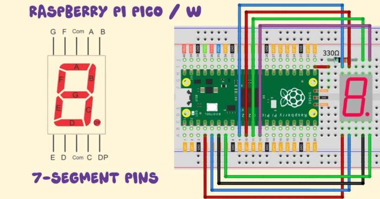
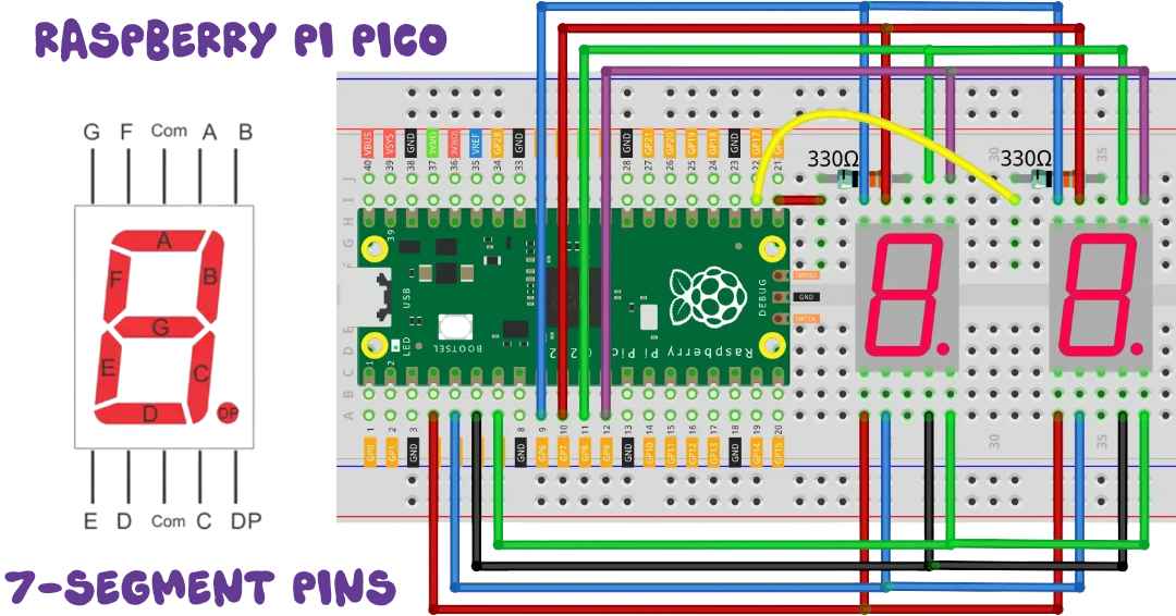
🔌 Wiring Diagram
🧩 Segment Connections (shared for both digits)
| Segment | GPIO Pin |
|---|---|
| a | GP0 |
| b | GP1 |
| c | GP2 |
| d | GP3 |
| e | GP4 |
| f | GP5 |
| g | GP6 |
| dp | GP7 |
🧩 Digit Selection Pins
| Display | Common Cathode Pin | GPIO |
|---|---|---|
| Left | COM1 | GP16 |
| Right | COM2 | GP17 |
Tip: Use resistors (220Ω) between GPIOs and segment pins to avoid damaging the Pico.
💻 The Python Code
Open Thonny IDE, connect your Pico, and paste the following code:
from machine import Pin
import utime

# Segment pins: a to dp → GPIO 0 to 7
segment_pins = [0, 1, 2, 3, 4, 5, 6, 7]
segments = [Pin(pin, Pin.OUT) for pin in segment_pins]

# Digit control pins → GPIO 16 and 17
digit_pins = [Pin(16, Pin.OUT), Pin(17, Pin.OUT)]  # 0 = ON

# Segment patterns for 0–9 (1 = ON for common cathode)
digit_patterns = [
    (1, 1, 1, 1, 1, 1, 0, 0),  # 0
    (0, 1, 1, 0, 0, 0, 0, 0),  # 1
    (1, 1, 0, 1, 1, 0, 1, 0),  # 2
    (1, 1, 1, 1, 0, 0, 1, 0),  # 3
    (0, 1, 1, 0, 0, 1, 1, 0),  # 4
    (1, 0, 1, 1, 0, 1, 1, 0),  # 5
    (1, 0, 1, 1, 1, 1, 1, 0),  # 6
    (1, 1, 1, 0, 0, 0, 0, 0),  # 7
    (1, 1, 1, 1, 1, 1, 1, 0),  # 8
    (1, 1, 1, 1, 0, 1, 1, 0)   # 9
]

# Show a digit on either display
def display_digit(display_index, number):
    # Turn off both displays before updating
    digit_pins[0].value(1)
    digit_pins[1].value(1)

    # Set segment pattern
    pattern = digit_patterns[number]
    for seg, val in zip(segments, pattern):
        seg.value(val)

    # Enable the selected display
    digit_pins[display_index].value(0)
    utime.sleep_us(500)
    digit_pins[display_index].value(1)

# Main loop: count from 00 to 99 quickly
while True:
    for tens in range(10):
        for ones in range(10):
            start = utime.ticks_ms()
            while utime.ticks_diff(utime.ticks_ms(), start) < 100:  # Speed control
                display_digit(0, tens)
                display_digit(1, ones)
🎯 What Happens?
- Your display will count from
00to99quickly. - The code refreshes each digit very fast using multiplexing.
- The count is controlled by a
100 msdelay for each number.
🧪 Try This!
- Change
100to50to make it even faster! - Modify the segment pattern to create custom letters (e.g.,
H,E,L,P)
🔍 Code Explanation – Step by Step
Let’s break down the code into small parts so you understand what each part does:
🔹 1. Import Libraries and Set Pins
pythonCopyEditfrom machine import Pin
import utime
machinelets you control GPIO pins.utimeis used for delays to control timing.
🔹 2. Setup Segment Pins
pythonCopyEditsegment_pins = [0, 1, 2, 3, 4, 5, 6, 7]
segments = [Pin(pin, Pin.OUT) for pin in segment_pins]
- We’re using GPIO 0 to 7 to control segments a to dp.
segmentsis a list of pins set as outputs.
💡 These pins will send HIGH (1) or LOW (0) to turn segments ON or OFF.
🔹 3. Setup Display Selection Pins
pythonCopyEditdigit_pins = [Pin(16, Pin.OUT), Pin(17, Pin.OUT)] # 0 = ON
- These two GPIOs (16 and 17) control which 7-segment display is active.
- Only one display is turned ON at a time using multiplexing.
🔹 4. Digit Patterns for 0–9
pythonCopyEditdigit_patterns = [
    (1, 1, 1, 1, 1, 1, 0, 0),  # 0
    (0, 1, 1, 0, 0, 0, 0, 0),  # 1
    ...
]
- Each number has a specific segment combination.
1means the segment is ON,0is OFF (because we use a common cathode display).
For example, to show 0, all segments except g and dp are ON.
🔹 5. Function to Display One Digit
pythonCopyEditdef display_digit(display_index, number):
    digit_pins[0].value(1)
    digit_pins[1].value(1)
- Turns both displays OFF before starting — this avoids ghosting or overlapping numbers.
pythonCopyEdit    pattern = digit_patterns[number]
    for seg, val in zip(segments, pattern):
        seg.value(val)
- Applies the pattern (which segments to turn on) for the given digit.
pythonCopyEdit    digit_pins[display_index].value(0)
    utime.sleep_us(500)
    digit_pins[display_index].value(1)
- Turns ON the selected display (
0= ON). - Waits a tiny bit (
500 µs) so the digit stays visible. - Then turns it OFF again.
💡 This function is called many times per second to simulate both digits being on.
🔹 6. Main Counter Loop
pythonCopyEditwhile True:
    for tens in range(10):
        for ones in range(10):
- Loops from
00to99using nested loops for tens and ones digits.
pythonCopyEdit            start = utime.ticks_ms()
            while utime.ticks_diff(utime.ticks_ms(), start) < 100:
                display_digit(0, tens)
                display_digit(1, ones)
- For every number (like 42), the digits
4and2are displayed repeatedly for100 milliseconds. - This refreshes the digits fast enough to appear stable to your eyes.
🎯 Summary
| Part of Code | What It Does |
|---|---|
segment_pins | Set GPIOs for segments a–dp |
digit_pins | Control which digit is active |
digit_patterns | Tell which segments to light for 0–9 |
display_digit() | Lights up one digit at a time |
while True loop | Counts from 00 to 99 on repeat |
✅ Bonus Tip:
Want to show only one number (like temperature or score)?
Just change the code to update only when a value changes, not continuously loop.
🛠️ Troubleshooting Tips
| Issue | Solution |
|---|---|
| Only one display lights | Check common pins (GP16/GP17) and grounding |
| Numbers look garbled | Make sure segment pins are wired in correct order |
| Segments are dim | Use external power and proper resistors |
🌟 Conclusion
This project is a great way to learn how microcontrollers communicate with displays. Once you’ve mastered this, you can go further by adding:
- Buttons to manually increase the count
- Displaying temperature or sensor data
- Converting it into a mini stopwatch or timer